1.2. Data Flow Diagram
This section describes the Data Flow Diagram for RMM.
1.2.1. Target of Evaluation
In this threat model, the target of evaluation is the Realm Management Monitor (RMM) in a system context for an Arm A-Class CPU with Realm Management Extension, as shown on Figure 1. Everything else on Figure 1 is outside of the scope of the evaluation.
RMM can be configured in various ways. In this threat model we consider only the most basic configuration. To that end we make the following assumptions:
RMM image is run from either ROM, on-chip trusted SRAM or off-chip DRAM. Any memory shared with EL3 Firmware is located inside on-chip trusted SRAM. If RMM runs from off-chip DRAM, then RMM is vulnerable to DRAM attacks (such as rowhammer) and attacks which can probe and tamper off-chip memory.
No experimental features are enabled. We do not consider threats that may come from them.
RME hardware threats and threats covered by the RMM ABI will be covered in a dedicated Security Risk Analysis document (to be published in the future). Although there is some overlap with threats mitigated by RME hardware and RMM ABI, this threat model focuses on covering threats specific to the RMM implementation and associated data flows.
1.2.2. Data Flow Diagram
Figure 1 shows a high-level data flow diagram for RMM. The diagram shows a model of the different components of a RMM system and their interactions with other FW/SW components. A description of each diagram element is given in Table 1. In the diagram, the red broken lines indicate trust boundaries. Components outside of the broken lines are considered untrusted by RMM. Components inside the broken lines must be trusted by RMM, as they provide security foundations for its functionality.
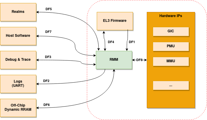
Diagram Element |
Description |
|---|---|
DF1 |
At boot time, EL3 Firmware configures RMM through
parameters stored in registers x0 to x3. It also
passes a Boot Manifest using secure shared memory.
|
DF2 |
RMM log system framework outputs debug messages
over a UART interface.
|
DF3 |
Debug and trace IP on a platform can allow access
to registers and memory of RMM.
|
DF4 |
Interface for RMM-EL3 communication as per documented
in RMM-EL3 Runtime Interface. RMM trusts EL3,
which is part of a trusted subsystem.
|
DF5 |
Realm software can interact with RMM to request
services through the RSI (Realm Service Interface).
This also includes the PSCI interface.
|
DF6 |
Regardless of the type of memory from where RMM is
executed, off-chip dynamic RAM (considered
Non-Secure) may be used to store large data
structures. This memory might be subject to different
attacks.
|
DF7 |
NS Host interacts with RMM by issuing SMCs that are
then forwarded from EL3 Firmware to RMM.
|
DF8 |
This path represents the interaction between RMM and
various hardware IPs such as MMU controller and GIC.
At boot time, RMM configures/initializes the IPs and
interacts with them at runtime through interrupts
and registers.
|