2. MMU setup and memory management design in RMM
This document describes how the MMU is setup and how memory is managed by the RMM implementation.
2.1. Physical Address Space
The Realm Management Extension (FEAT_RME) defines four Physical Address
Spaces (PAS):
Non-secure
Secure
Realm
Root
RMM code and RMM data are in Realm PAS memory, loaded and allocated to Realm PAS at boot time by the EL3 Firmware. This is a static carveout and it is never changed during the lifetime of the system.
The size of the RMM data is fixed at build time. The majority of this is the granules array (see Granule state tracking below), whose size is configurable and proportional to the maximum amount of delegable DRAM supported by the system.
Realm data and metadata are in Realm PAS memory, which is delegated to the Realm PAS by the Host at runtime. The RMM ABI ensures that this memory cannot be returned to Non-secure PAS (“undelegated”) while it is in use by the RMM or by a Realm.
NS data is in Non-secure PAS memory. The Host is able to change the PAS of this memory while it is being accessed by the RMM. Consequently, the RMM must be able to handle a Granule Protection Fault (GPF) while accessing NS data as part of RMI handling.
2.2. Granule state tracking
The RMM manages a data structure called the granules array, which is stored in RMM data memory.
The granules array contains one entry for every Granule of physical memory which was in Non-secure PAS at RMM boot and can be delegated.
Each entry in the granules array contains a field granule_state which records the state of the Granule and which can be one of the states as listed below:
NS: Not Realm PAS (i.e. Non-secure PAS, Root PAS or Secure PAS)
Delegated: Realm PAS, but not yet assigned a purpose as either Realm data or Realm metadata
RD: Realm Descriptor
REC: Realm Execution Context
REC aux: Auxiliary storage for REC
Data: Realm data
RTT: Realm Stage 2 translation tables
As part of RMI SMC handling, the state of the granule can be a pre-condition and undergo transition to a new state. For more details on the various granule states and their transitions, please refer to the Realm Management Monitor (RMM) Specification.
For further details, see:
enum granule_statestruct granule
2.3. RMM stage 1 translation regime
RMM uses the FEAT_VHE extension to split the 64-bit VA space into two
address spaces as shown in the figure below:
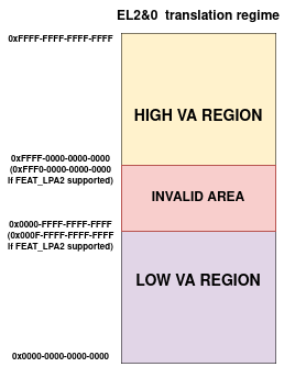
The Low VA range: it expands from VA 0x0 up to the maximum VA size configured for the region (with a maximum VA size of 48 bits or 52 bits if
FEAT_LPA2is supported). This range is used to map the RMM Runtime (code, data, shared memory with EL3-FW and any other platform mappings).The High VA range: It expands from VA 0xFFFF_FFFF_FFFF_FFFF all the way down to an address corresponding to the maximum VA size configured for the region. This region is used by the Stage 1 High VA - Slot Buffer mechanism as well as the Per-CPU stack mapping.
There is a range of invalid addresses between both ranges that is not mapped to any of them as shown in the figure above. TCR_EL2.TxSZ fields controls the maximum VA size of each region and RMM configures this field to fit the mappings used for each region.
The 2 VA ranges are used for 2 different purposes in RMM as described below.
2.3.1. Stage 1 Low VA range
The Low VA range is used to create static mappings which are shared across all the CPUs. It encompasses the RMM executable binary memory and the EL3 Shared memory region.
The RMM Executable binary memory consists of code, RO data and RW data. Note that the stage 1 translation tables for the Low Region are kept in RO data, so that once the MMU is enabled, the tables mappings are protected from further modification.
The EL3 shared memory, which is allocated by the EL3 Firmware, is used by the RMM-EL3 communications interface. A pointer to the beginning of this area is received by RMM during initialization. RMM will then map the region in the .rw area.
The Low VA range is setup by the platform layer as part of platform initialization.
The following mappings belong to the Low VA Range:
RMM_CODE
RMM_RO
RMM_RW
RMM_SHARED
Per-platform mappings can also be added if needed, such as the UART for the FVP platform.
2.3.2. Stage 1 High VA range
The High VA range is used to create dynamic per-CPU mappings. The tables used for this are private to each CPU and hence it is possible for every CPU to map a different PA at a specific VA. This property is used by the slot-buffer mechanism as described later.
In order to allow the mappings for this region to be dynamic, its translation tables are stored in the RW section of RMM, allowing for it to be modified as needed.
For more details see xlat_high_va.c file of the xlat library.
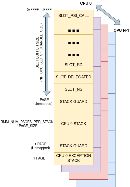
The diagram below shows the memory layout for the High VA region.
2.3.2.1. Stage 1 High VA - Slot Buffer mechanism
The RMM provides a dynamic mapping mechanism called slot-buffer in the high VA region. The assigned VA space for slot-buffer is divided into slots of GRANULE_SIZE each.
The RMM has a fixed number of slots per CPU. Each slot is used to map memory of a particular category. The RMM validates that the target physical granule to be mapped is of the expected granule_state by looking up the corresponding entry in granules array.
The slot-buffer mechanism has slots for mapping memory of the following types:
Realm metadata: These correspond to the specific Realm and Realm Execution context scheduled on the PE. These mappings are usually only valid during the execution of an RMI or RSI handlers and are removed afterwards. These include Realm Descriptors (RDs), Realm Execution Contexts (RECs), Realm Translation Tables (RTTs).
NS data: RMM needs to map NS memory as part of RMIs to access parameters passed by the Host or to return arguments to the Host. RMM also needs to copy Data provided by the Host as part of populating the Realm data memory.
Realm data: RMM sometimes needs to temporarily map Realm data memory during Realm creation in order to load the Realm image or access buffers specified by the Realm as part of RSI commends.
The slot-buffer design avoids the need for generic allocation of VA space. The rationalization of all mappings ever needed for managing a realm via slots is only possible due to the simple nature of the RMM design - in particular, the fact that it is possible to statically determine the types of objects which need to be mapped into the RMM’s address space, and the maximum number of objects of a given type which need to be mapped at any point in time.
During Realm entry and Realm exit, the RD is mapped in the “RD” buffer slot. Once Realm entry or Realm exit is complete, this mapping is removed. The RD is not mapped during Realm execution.
The REC and the rmi_rec_run data structures are both mapped during Realm execution.
As the slots are mapped on the High VA region, each CPU has its own private translation tables for such mappings, which means that a particular slot has a fixed VA on every CPU. Since the Translation tables are private to a CPU, the mapping to the slot is private to the CPU. This allows the interruption and migration of a REC (vCPU) to another CPU with live memory allocations in RMM. An example of this scenario is when the Realm attestation token is being created in RMM, a pending IRQ can cause RMM to yield to NS Host with live memory allocations in MbedTLS heap. The NS Host can schedule the REC on another CPU and, since the mapping for the memory allocations remain at the same VA, the interrupted realm token creation can continue.
The slot-buffer implementation in RMM also has some performance optimizations like caching of TTE’s to avoid walking the Stage 1 translation tables for every map and unmap operation.
As an alternative to using dynamic mappings as required for the RMI command, the approach of maintaining static mappings for all physical memory was considered, but rejected on the grounds that this could permit arbitrary memory access for an attacker who is able to subvert RMM execution.
The xlat lib APIs are used by the slot-buffer to create dynamic mappings.
These dynamic mappings are stored in the high VA region’s xlat_ctx
structure and marked by the xlat library as TRANSIENT. This helps xlat lib to
distinguish valid Translation Table Entries from invalid ones as otherwise the
unmapped dynamic TTEs would be identical to INVALID ones.
For further details, see:
enum buffer_slotlib/realm/src/buffer.c
2.3.2.2. Per-CPU stack mapping
Each CPU maps its stack to the High VA region which means that the stack has same VA on all the CPUs and it is private to the CPU. At boot time, each CPU calculates the PA for the start of the stack and maps it to the designated High VA address space.
The per-CPU VA mapping also includes a gap at the end of the stack VA to detect any stack underflows. The gap has a page size.
RMM also uses a separate Per-CPU stack to handle exceptions and faults. This stack is allocated below the general one, and it allows for RMM to be able to handle a stack overflow fault. There is another page gap of unmapped memory between both stacks to harden security.
The rest of the VA space available below the exception stack is unused and therefore left unmapped. The stage 1 translation library will not allow to map anything there.
2.4. Stage 1 translation library (xlat library)
The RMM stage 1 translation management is taken care of by the xlat library.
This library is able to support up to 52-bit addresses and 5 levels of
translation (when FEAT_LPA2 is enabled).
The xlat library is designed to be stateless and it uses the abstraction of
translation context, modelled through the struct xlat_ctx. A translation
context stores all the information related to a given VA space, such as the
translation tables, the VA configuration used to initialize the context and any
internal status related to such VA. Once a context has been initialized, its
VA configuration cannot be modified.
At the moment, although the xlat library supports creation of multiple contexts, it assumes that the caller will only use a single context per CPU for a given VA region. The library does not offer support to switch contexts on a CPU at run time. A context can be shared by several CPUs if they share the same VA configuration and mappings, like on the low va region.
Dynamic mappings can be created by specifying the TRANSIENT flag. The
high VA region create dynamic mappings using this flag.
For further details, see lib/xlat.
2.5. RMM executable bootstrap
The RMM is loaded as a .bin file by the EL3 loader. The size of the sections in the RMM binary as well as the placing of RMM code and data into appropriate sections is controlled by the linker script in the source tree.
Platform initialization code takes care of importing the linker symbols
that define the boundaries of the different sections and creates static
memory mappings that are then used to initialize an xlat_ctx structure
for the low VA region. The RMM binary sections are flat-mapped and are shared
across all the CPUs on the system. In addition, as RMM is compiled as a
Position Independent Executable (PIE) at address 0x0, the Global Offset
Table (GOT) and other relocations in the binary are fixed up with the right
offsets as part of boot. This allows RMM to be run at any physical address as
a PIE regardless of the compile time address.
For further details, see:
runtime/linker.ldsplat/common/src/plat_common_init.cplat/fvp/src/fvp_setup.c